This guide illustrates how SIP, Audio and Data traffic is transmitted over the network when 3CX Phone System is used. This will depend on the backend infrastructure and network topology, and this guide helps administrators understand how 3CX operates in different scenarios. If a combination of topologies is used, 3CX Phone System will route traffic as needed.
Terms used in this guide:
- SIP – This is the protocol used to initiate and control the communication between 2 parties.
- Audio – Once the call has been established, audio can be sent using a different route. The term Audio is used to incorporate the data that is transmitted during the call, including video and fax data. This is also known as SDP.
- VoIP – refers to both SIP and Audio as described above
- Data – This incorporates all other data which is not related to VoIP, including data such as web traffic, email traffic etc.
This guide covers the following types of networks:
- Simple network: VoIP and Data are transmitted within a single network.
- Routed networks: VoIP and Data communication are transmitted on two networks (or V-LANs). A router takes care of routing packets between the 2 networks.
- Segregated VoIP network: VoIP is transmitted on a separate network. Routing is done by having 2 network cards attached to server running 3CX Phone System.
- Public network – NAT: A network in which network traffic is transmitted over the public network directly to another network.
- Public network – VPN: A network that is connected via a LAN-2-LAN VPN to another network.
- Multiple internet gateways: Scenario where VoIP traffic transmitted over a separate internet network.
Simple network
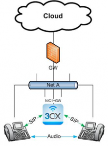
This is the most common scenario, where all the devices are located in the same network, and both VoIP and Data share the same network.
SIP traffic is handled by the 3CX Phone System server and audio passes directly from the VoIP endpoints. 3CX Phone System connects to the network using one network card with a default gateway.
Routed networks
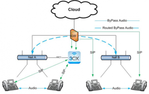
In a routed network you typically have two or more networks which are already segregated, such as for example one network is used by one department and another network is used by another department, or when you want VoIP traffic to be on a separate network than Data traffic.
In this scenario, the router takes care of routing traffic from one network to the other. 3CX Phone System is connected to 1 network, and will be used to create the communication between any 2 endpoints (the SIP part). Once the connection has been established, Audio is transmitted directly between endpoints. If the endpoints are on different networks, the router will take care of routing Audio traffic accordingly.
Background: 3CX Phone System identifies registrations received from a different subnet. 3CX Phone System assumes that there is a route to the second network and enables “By-Pass-Audio” for this setup.
If you have issues related to calling from one network to the other, you need to check traffic at the router level as that is the main point of communication.
Segregated VoIP network
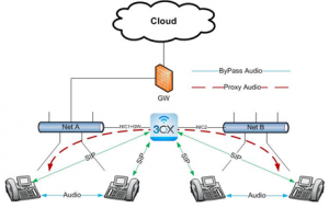
Some routers do not support multiple internal networks. However, the administrator would still want to have a second network, which is normally used only for VoIP traffic. This can be done by adding another network card to the server running 3CX Phone System.
The diagram above shows 3CX Phone System with 2 network cards connected to 2 different networks. Network A is used for Data traffic, although VoIP traffic can still be transmitted over this network, such as when using soft-phones. Network B is the network which is used for VoIP traffic. 3CX Phone System is connected to both networks, since its server has 2 network cards.
IMPORTANT: In this scenario, you need to make the following configuration changes.
- The network interface on the 3CX Server that connects to the router/gateway must contain a Default Gateway specified in Network adapter settings.
- The Network adapter interface on 3CX Phone System that connects to Network B must NOT have a default gateway specified. This entry should be blank.
Background: The 3CX Phone System detects, that there is no known route from Network A to B and vice versa. Therefore the only way to pass audio between them networks is via the 3CX PBX itself and the PBX enables “Proxy Audio” when a call flows between the networks. Inside each network the audio is passes in “By-Pass Audio”
Public Network – NAT
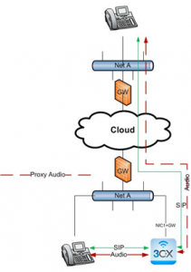
The above diagram shows a remote endpoint (home office or VoIP provider) connected to the 3CX Server via the Internet. The remote end is completely outside of the company network.
In this scenario, both SIP and Audio is routed through the PBX for calls where one endpoint is on the LAN and the second endpoint is on the WAN. The same happens when both endpoints are on the WAN. This occurs also when the 2 endpoints are using the same Public IP address, since the 2 endpoints might be on separate internal networks which might not be able to route traffic between each other.
NAT port forwarding is performed on the company gateway. The remote endpoint can communicate with 3CX Phone System as an external extension. 3CX Phone System detects this as a remote endpoint and will make use ports configured for the external Leg when constructing the SDP for audio. Read more about Port Forwarding with 3CX Phone System here.
Some home routers might also have SIP ALG enabled which may need to be disabled. For example, on Thomson routers SIP ALG will need to be disabled using telnet.
If all these things fail, you can always use 3CX SIP Proxy Manager or use 3CX Phone for Windows, 3CXPhone for Android or 3CXPhone for iPhone.
Public Network – VPN
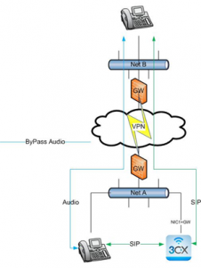
This example shows a remote user/network connected via VPN. In reality, 3CX Phone System sees this “remote” user as just another local user in a different network. The routing in this case is made by the router/gateway. This becomes a LAN to LAN connection over the internet. For the 3CX Phone System the same rule are applied as for a “Routed Network”.
Since the endpoints on both networks are registering using their IP address, 3CX Phone System will only setup the call (SIP), and instructs the endpoints to send Audio directly to each other. This saves bandwidth and overhead.
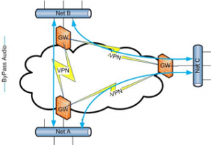
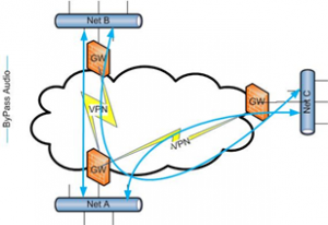
Note: If you have multiple LAN to LAN connections between different locations, VPN routing must be configured correctly. For example, if you connect 3 locations (Network A, B and C), each of these 3 networks can have a direct connection to each other or one of the VPN Gateways must be configured to route traffic to the correct network. In our example, the VPN router in Net A is the gateway distributing routing to the other networks. In this case, the router in Net B needs to be configured to send to Net C through Net B. Same applies for Net C to Net B.
Multiple internet gateways (used by ISPs that offer VoIP Services)
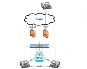
There are installations with 2 separate routers/gateways – one for Internet access and the other solely for VoIP. This is used to segregate VoIP traffic from data traffic.
The server must have two network cards. NIC 1 is connected to the gateway or interface that connects to the Internet. This NIC interface MUST have a Default Gateway specified. NIC 2 is connected to the gateway or interface that connects to the VoIP networks of the ISP. This network interface must NOT have a default gateway configured in Windows.
How will traffic for VoIP be sent to the interface without a default gateway?
Step 1: Enable “Windows Routing and Remote access” on your Server and let RRAS route the traffic destined to the VoIP gateway out from the VoIP interface. Routing and remote access can be enabled on Windows Server 2008 by going to Server Manager Add Roles Select Network Policy and Access Services Select Routing and remote access services Checkboxes.
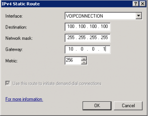
Step 2: A static route must be created. Configure it as follows:
- Interface: As an interface we will select NIC2 – the VoIP VPN interface on the Windows Server that is a point to point connection with the ISP’s VoIP gateway or interface.
- Destination: The destination IP of the VoIP Provider services that can be reached via the VoIP Interface.
- Network Mask: The network subnet mask
- Gateway: Here is where we will put the default gateway. In this case we will put the IP Address of the VoIP Gateway Interface. This will be the replacement factor of putting the default gateway in Windows Network Adapter NIC 2.
- Metric: 256 to indicate highest cost.
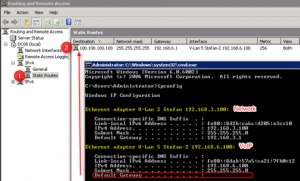
The above screenshot shows that the NIC connected to the Internet Gateway has a Default Gateway specified whilst the adapter that is connected to the VoIP Gateway does not. However, as a replacement we will use the services of Windows Routing and remote access to route the traffic to the Default gateway for the VoIP Interface.
